From box to first pixels.
Six steps, no surprises. A Dig-Octa stack goes together with a screwdriver, and the firmware is already on the board. Plan for about 45 minutes the first time, mostly spent on tidy wiring.
Plan your stack
Pick the powerboard first, it sets the personality of the build. Power-5: 50A with 12 pluggable fused outputs that stay reachable in a stack. Power-7: 50A and 16 fused screw terminals for prop-heavy displays. Power-7HC: the same density at 100A with bolt-down inputs. Power-5HV: 30A for 24–48V LEDs. One brainboard drives 8 channels and roughly 2,000 LEDs in WLED at full frame rate; if you need more channels, plan a second brainboard rather than a bigger one.
A 24V stack can feed up to 12 brainboards through QPowerPost alone; at 5V plan on 3. Mixed-voltage stacks are fine and the brainboards always pick the highest rail automatically.
Stack the boards
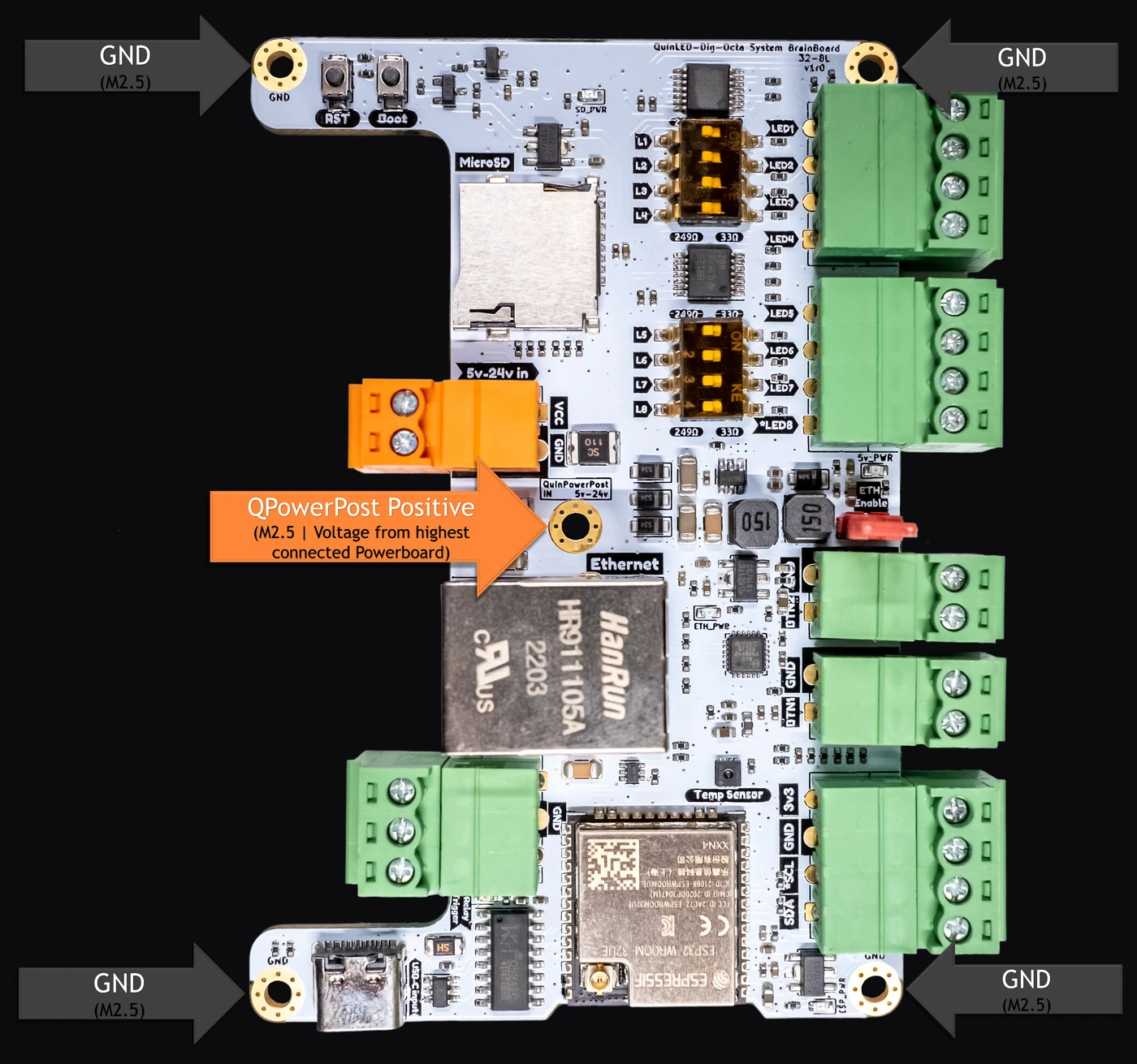
Stand the powerboard on its M3 standoffs (never flat on a surface; the included feet keep solder joints clear and air moving). Then place the brainboard on the five M2.5 QPowerPost standoffs: four outer posts are ground, the center post carries VCC up to the brainboard. That's the whole power bus. Powerboards can only send, brainboards can only receive, enforced in hardware on both sides, so there is no wrong order to get anxious about.
Stacking more boards? Powerboard-to-powerboard uses the outer M3 posts, and connecting all five M2.5 posts builds one continuous QPowerPost bus through the whole tower.
Power-7 and Power-7HC fuses sit under their tall screw terminals, so keep those as the top powerboard or wire them before stacking. A brainboard above them blocks nothing.
Wire the power
Connect your PSU to all three powerboard inputs (two M5 bolts on the 7HC) with 12 AWG or thicker wire. Fewer input cables means a lower current ceiling, so wire them all even for smaller builds. Tighten the barrier terminals onto ferrules or SV5.5-4 fork crimps, not loose strands.
The brainboard itself needs no power wiring at all on a stack: it drinks from the QPowerPost standoffs. Running a brainboard solo? Feed it through USB-C or the orange 5–24V terminal. All three inputs may be connected at the same time, even at different voltages; the board switches between them without rebooting.
One power supply per powerboard, always. Two PSUs on one board can end in a dangerous load-sharing failure. One big PSU feeding several powerboards is fine.
Connect the LEDs
Power and data travel separately, and that's the point of the system. Each LED run's + and − land on a fused powerboard output; pick the fuse for the wire you used (the included 5A and 10A assortment covers typical runs, and lower values are always fine). The data wire for each run comes from the brainboard's two 4-pin LED terminals, eight data channels in total; power and ground always come from the powerboard.
Plan around 500 to 600 ws281x pixels per channel to keep WLED above 40 FPS. Long 3-wire runs to xConnect props? Flip that channel's DIP switch from 249 Ω to 33 Ω and a 10m / 32ft data run is easy.
Spread the load: a front feed carries about 4A, a middle injection about 8A. Interleave heavy and light runs across the board, and plan the feeds with the ultimate power injection guide.
First boot and WLED
Switch the PSU on. The voltage display wakes up, and the brainboard boots the WLED that shipped on it, Ethernet already enabled with the QuinLED-Dig-Octa profile. Plug in a network cable and it just appears on your LAN; on Wi-Fi, join the WLED-AP hotspot (password wled1234) and point it at your network.
Three settings finish the job in Config → LED Preferences:
- Outputs: add one entry per LED channel you wired, with its GPIO preset untouched.
- Counts: set the real pixel count per output (the board ships with 30 per channel for testing).
- Brightness limiter: raise it to match your PSU, or disable it once your fusing is right.
Updating later takes two minutes over USB-C at install.quinled.info, including Audio Reactive builds for the v2 microphone header.
Flashed a generic WLED build over USB? Set the Ethernet type to "QuinLED-Dig-Octa" in WiFi settings and the wired port comes back.
Grow it into a show
WLED's local effects already cover a lot. When you want choreography, the brainboard speaks the show protocols natively: stream from xLights, Vixen or Madrix over E1.31 or Art-Net (use the Ethernet port; real-time pixel data drowns Wi-Fi), mirror several brainboards with WLED Sync, or chain them into one canvas with DDP. Prefer ESPixelstick v4? It's fully supported, and its hybrid mode plays shows from the MicroSD card while FPP only sends sync.
Two finishing touches worth wiring: a relay board on the relay terminal lets WLED cut the big PSU on the AC side while USB-C keeps the brainboard reachable at 300–500mA. And the v2 microphone header takes an INMP441 for sound-reactive effects.
Each brainboard is its own network device. Give every one a fixed IP or hostname before show season; future you says thanks.
Answers are one click away.
The Brainboard FAQ covers the questions that actually come up: shared pins, PoE, standby power, capacity math. For everything else there's a Discord full of people who built this before you.